Understanding Surge Protection For LED Lighting Systems
Surge Protection Overview. Voltage surges have a huge destructive impact upon electronic equipment, including LED lighting systems. They wear out LED drivers and distribution panels prematurely and i…
Surge Protection Overview
Voltage surges have a huge destructive impact upon electronic equipment, including LED lighting systems. They wear out LED drivers and distribution panels prematurely and increase service interruptions to LED lighting. Beyond material damage to the luminaires, voltage surges caused by lightning, for example, can trigger or break protective devices in the circuit boards of lighting distribution panels.
The vulnerability of electronic lighting systems to over-voltages is widely recognized in technical literature, and different international regulations and standards specify the need for lighting protection. This document explains the causes of lightning over- voltages and how they affect lighting installations. It also proposes solutions to maximize protection performance and continuity of service.
Public lighting installations are exposed to the environment. Located where continuity of service is essential, it is crucial that these installations are protected against lightning and over-voltages.
Investing in protection can extend luminaire lifetime, improve public services, and greatly reduce overall operating and infrastructure costs
Building-in protection
What are transient or surge over-voltages?
Surge over-voltages are spikes that can reach tens of kilovolts but last for only a few microseconds. Despite their short duration, their high energy content may cause serious problems to electronic equipment connected to the electricity network — from premature aging to destruction — resulting in service disruptions and costly repairs.

Figure 1 - Transient 'surge' over-voltage
Voltage surges have several causes. For example, lightning discharges that directly strike the distribution line of a building, or its lightning rod, can induce electromagnetic fields that generate voltage spikes in nearby lighting installations. Long outdoor distribution power lines are highly susceptible to the direct effects of lightning strikes, with large currents from the lightning being conducted in the power lines. It’s also common for non-weather phenomena to cause voltage spikes in adjacent lines — for instance, switching devices (contactors) inside electrical cabinets, or the disconnection of transformers, motors and other inductive loads or high power equipment (generators, welders) coupling energy on shared branch circuits connected to sensitive electronic equipment.
Surge over-voltages have two modes of circulation: common and differential as illustrated in Figure 2. Common-mode over-voltages appear between the live conductors and earth/ ground: for example, line-to-earth or neutral-to-earth. Differential-mode over-voltages circulate between live conductors: line-to-line or line-to-neutral. A well-protected luminaire should integrate protection for both modes.
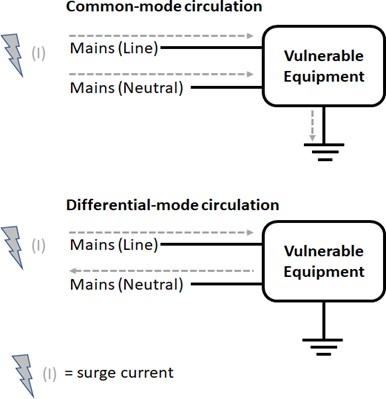
Figure 2 - Definition of common and differential-mode currents
Surge over-voltage protection is provided by installing a surge protection device (SPD) on the vulnerable line. In the event of a surge over-voltage, the protective device will divert excess energy to earth/ground, thus limiting the peak voltage to a tolerable level for the electrical equipment connected downstream.
An SPD can be installed in parallel or series.
When the SPD is connected in series it acts like a fuse. So, when the priority is to protect the electronic components down the line from further damage, as is the case in most outdoor applications, series connection is preferred.
When connected in parallel, the luminaire continues to function even after the SPD is damaged, leaving the electronic components down the line unprotected. So, when continuity of functioning is preferred over protection of components down the line, parallel connection can be used.
The SPD will be degraded after weathering a number of spikes above its specified threshold voltage level. A certified SPD is provided with an indicator flag that shows when the SPD is no longer functional. It is vital that the indicator be regularly monitored as part of general maintenance and replaced when the indicator shows the SPD is non- functional.
Protecting against the effects of surge over-voltages in LED lighting systems
An SPD acts as a voltage-controlled switch. When the voltage surge is lower than the SPD activation voltage, the component is passive. On the other hand, when the voltage surge exceeds the activation voltage, the SPD diverts the surge energy and prevents it from damaging the equipment. When choosing an SPD, consideration must be made of the equipment’s exposure to lightning, along with the maximum impulse voltage that the equipment needs to withstand.
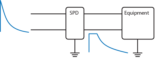
Figure 3 - Working principle of a surge protection device SPD
In general, the most effective approach to protect large installations of lighting equipment against surge over-voltages is by cascading multiple protective stages. Each stage combines the necessary balance between discharge capacity and voltage protection level. This way, a first stage (typically a ‘Type 1’ (Class I) or ‘Type 2’ (Class II) SPD) provides robustness, thus diverting most of a spike’s energy, while a second stage (typically a ‘Type 2’ (Class II) or ‘Type 3’ (Class III) SPD) provides ‘local’ protection. The peak voltage and current reaching the equipment always stay below the critical level. Installations have unique characteristics; therefore, SPD solutions should be tailored appropriately with proper lightning protection and earth grounding systems in place.
Of the causes of surges mentioned in international protection standards, the ones most likely to affect a public lighting system are:
- Direct lightning strikes on distribution lines (conducted through the power lines)
- Lightning strikes near a building/structure (creating induced surges)
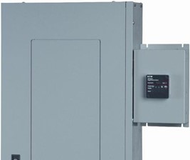
The protection solution is installed near the main circuit breaker in the distribution panel circuit board, in parallel to the main system. So, it diverts the energy of the surge to earth, limiting the voltage peak to a tolerable level for equipment connected downstream.
To guarantee proper protection of a luminaire, the distance between it and its protector circuit must be as short as possible. If the distance between a protected distribution panel and several luminaires is more than 20 meters, using a second protection stage is recommended, even if the protection level of the first stage seems to be sufficient.
Properly made earth ground connections are essential to the effective functioning of a lightning protection system. Earth ground connections must provide proper contact per industry electrical system construction standards. The connection resistance must be low, and the conductivity of the earth substrate material must allow efficient dissipation of surge energy.
Practical approach
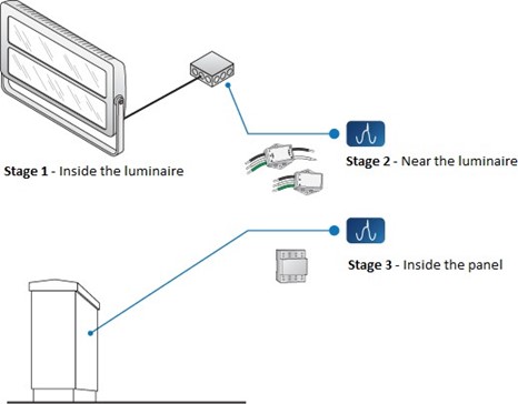
Figure 4 - Circuit protection solutions for luminaires and lighting distribution panels
Stage 1 Protection: Standard protection at luminaire level IEC61547 states that all luminaires should be protected from over-voltages up to 1 kV in differential mode and 2 kV in common mode. Type 3 (Class III) surge protective devices.
Stage 2 Protection: When designing installations, the area should be assessed for its vulnerability to lightning strikes. If the vulnerability is high, additional protection up to 10kV is recommended. In these cases, it is recommended to use an SPD, in addition to the standard protection at luminaire level. Type 2 (Class II) surge protective device.
Stage 3 Protection: In the most vulnerable environments, the SPDs can be installed in the service entrance panel. It protects not only surge over-voltages (max surge current of 40 kA) but also power-frequency over-voltages. Type 1 (Class I) surge protective devices.
Surge Protective Device (SPD) installation tips
Always refer to the SPD manufacturers installation instructions and best practices.
- For general purpose protection, install an SPD in each electrical panel to protect the connected equipment.
- Connect the SPD to a circuit breaker in the panel using the shortest possible wire length (no more than 6” wire length). Wires longer than 6 inches will reduce the surge protection capability of the SPD meaning it will let through higher voltage spikes than SPDs installed with shorter wires.
- Twist SPD wires together.
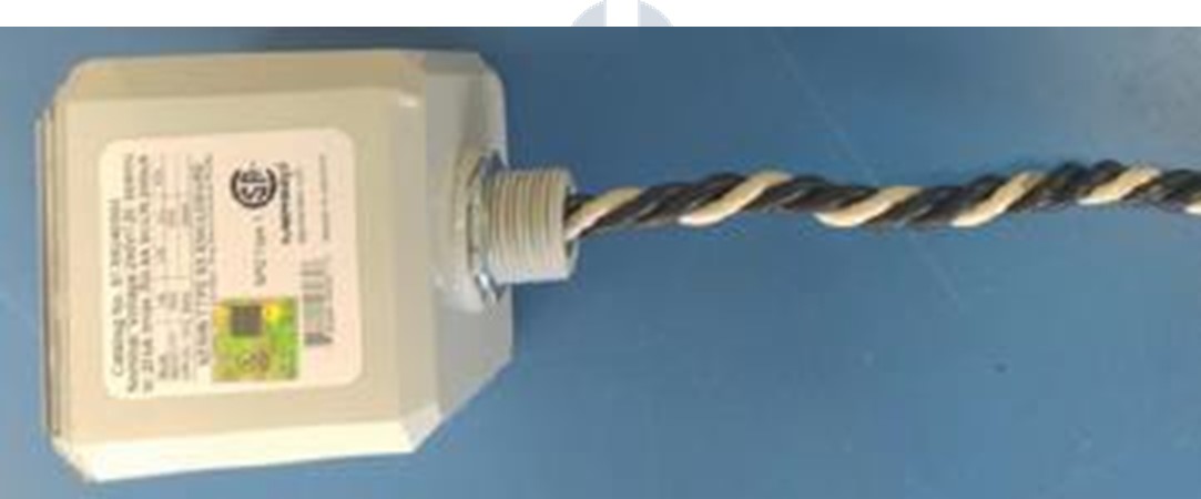
- Avoid sharp bends in SPD wiring.
- To minimize wire length, mount SPD directly on side of Panel or install SPD in panel (if supported by electrical panel).
Surge Protection Device (SPD) selection tips
Specification and Considerations for selecting panel connected SPDs:
- Choose a certified SPD to protect the branch circuit and the equipment connected to it. Always install SPDs in accordance with local electrical codes and per the SPD manufacturer’s instructions.
- The SPD should protect against common mode (Line-Earth, Neutral-Earth) and differential mode (Line-Neutral) surges.
- Select an SPD designed for the exact nominal operating voltage of the installation. An SPD designed for a higher operating voltage will not offer better protection.
- Low let through voltage / voltage protection rating (VPR). Target VPR:
- Common Mode (L Earth or N Earth): ≤1500V, lower is better
- Differential Mode (L N or L L), Preferred: ≤1000V, lower is better
- Differential Mode (L N or L L), Acceptable: ≤1200V, lower is better
- Note: L L spec applies when single phase loads are connected without a neutral wire, such as with 208V circuits in a 120/208V system.
- High surge voltage/current ratings (higher ratings will result in a longer life SPD).
- Certified SPDs have a Failure indication built in (often an indicator light or flag) to allow for easy visual inspection by maintenance personnel to determine whether the SPD is still functional. Regular inspection is vital. SPDs where the indicator shows the device is nonfunctional should be replaced immediately.
Further reading
Surge Protector Powercore Application Guide answer questions about using Surge Protector Powercore within a properly grounded cascaded surge protection system.
IEC TR 62066 - Surge over-voltages and surge protection in low-voltage AC power systems - General information.
IEEE C62.41-1991 - IEEE Recommended Practice on Surge Voltages in Low-Voltage AC Power Circuits
How Did We Do?
Surge Protector Powercore Application Guide