Table of Contents
Management Tool Introduction
Maps identify all KiNET interfaces ie: power/data supplies, switches, and luminaires in your installation so that ColorPlay 4 can accurately output light data.

1. Device Discovery and Map Creation
Maps identify all KiNET interfaces ie: power/data supplies and luminaires in your installation so that ColorPlay 4 & iPlayer 4 can accurately output light data. Additionally, maps allow you to group luminaires in various configurations to produce sophisticated light shows. There are two methods for creating maps: automatic mapping and manual mapping.
Automatic Mapping Process
Automatic mapping follows this basic workflow:
- Discover KiNET interfaces (power/data supplies).
- Discover the luminaires attached to each power/data supply.
Discover Interfaces
The first step in creating a map of your Ethernet network is to discover the KiNET interfaces (power/data supplies) installed on the network. Management Tool automatically discovers all power/data supplies via an Ethernet broadcast operation.
To discover power/data supplies on your lighting network:
- Connect your computer to the lighting network. If you need to configure your computer with a static IP address, set the IP address in the same lighting network. e.g. IP address 10.1.2.3 and a Subnet mask of 255.0.0.0 .
- Launch Management Tool:
• On Windows: Click the Start menu, and then select All Programs>Color Kinetics>Management Tool.
• On macOS: Click the Management Tool icon located on the Dock.
- When Management Tool launches, click the Discover Interfaces icon from the tool bar, or select Light View>Discover Interfaces from the menu. Management Tool queries the network and identifies all interfaces. When the operation is complete, the Discover Interfaces Wizard is displayed.
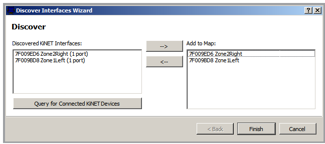
- Select an interface that you want to add to the map in the Discovered KiNET Interfaces list. Click the right arrow button, or double-click a highlighted interface, to move it onto the Add to Map panel.
• To remove an interface from the Add to Map panel, highlight the interface and click the left arrow button.
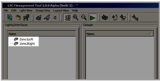
- Click Finish to close the wizard and add the interfaces to your map. The discovered interface is shown in the Lights/Interfaces panel in the Management Tool.
Discover Luminaires
The second step in creating a map is to query each power/data supply so that Management Tool can automatically discover any attached luminaires. Note that Chromasic luminaires, such as Flex Compact gen3 RGB, are discovered differently than Chromacore luminaires, such as Blast Powercore gen5 and ColorGraze IntelliHue Powercore.
To discover Chromasic luminaires:
- Click the Discover Lights icon in the tool bar to launch the Discover Lights Wizard.
- Select a power/data supply from the list, and click Next. Management Tool automatically discovers all nodes attached to the selected power/data supply.
- After discovery is complete, click Next, and then click Finish.
- Specify the layout, naming, and properties of your nodes:
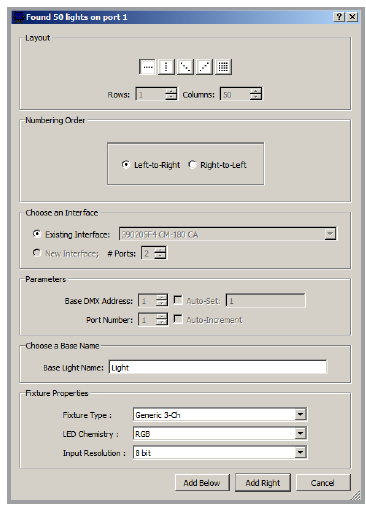
• Use the options in the Layout and Numbering Order panes to specify how your nodes are oriented.
• Type a name in the Base Name box, or use the default name.
• Use the Fixture Properties pane to match your nodes’ configuration.
• Click Add Below to add the nodes below the most recent luminaires on the map, or click Add Right to add the nodes to the right of the most recently added luminaires on the map. The nodes are added to the map and are shown in the layout panel.
- If you have nodes connected to more than one port on your power/data supply, repeat step 4 for all ports.
- Save the map by selecting File>Save Map.
Discovering Chromacore luminaires:
- Click the Discover Lights icon in the tool bar to launch the Discover Lights Wizard.
- Select a power/data supply from the list, and click Next. Light System Composer automatically discovers all luminaires attached to the selected power/data supply.
- After discovery is complete, click Next. The Read Light DMX Addresses window is displayed.
- Click Read Existing Addresses. Management Tool reads the DMX addresses of all luminaires attached to the power/data supply. If there are no conflicting DMX addresses, you will see the message “The lights are uniquely addressed”. Click Finish to exit the wizard.
- Click File>Save Map to save your map.
Manual Map Creation
The Add tools, located on the tool bar, offer offline mapping functionality. With the Add tools, you can add power/data supplies and luminaires to an existing map when an installation expands, eliminating the need to create a new map from scratch. You can also create placeholder maps that can be associated with installations at a later time, allowing you to create maps and light shows prior to the completion of an actual lighting project.
To manually add power/data supplies to a map:
- In Management Tool, click the Add Interface button in the tool bar, or select Light View>Add Interface from the menu. The Interface Type window is displayed.
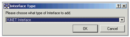
- Select KiNET interface from the list, and click OK.
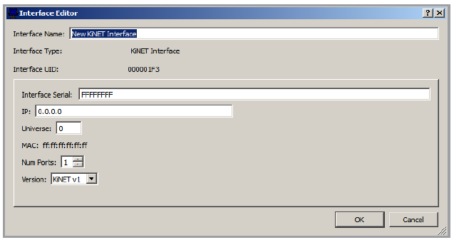
- The Interface Editor window is displayed. Type a descriptive name in the Interface Name box.
- If you know the serial number or IP address of the power/data supply, type the correct information in the Interface Serial box and the IP box, respectively. If you do not have this information, leave the default value in the appropriate box.
- Use the Num Ports box to specify the number of ports on your power/ data supply.
- Click OK. The power/data supply is added to the Lights/Interfaces panel.
- The interface icon is shown with a gray background, indicating that it is not yet associated with a discovered interface.
To manually map flexible string luminaires:
- Click the Add String button in the tool bar, or select Light View>Add String from the menu. The Create String dialog box is shown.
- Specify the layout, naming, and properties of your nodes:
• Use the options in the Layout and Numbering Order panes to specify how your nodes are oriented.
• Use the Choose an Interface pane to select an existing power/data supply, or to specify the number of ports on a power/data supply that is not already part of your map.
• Set the Base DMX Address and Port Number. Select the Auto-Set check box to set to the next available DMX address. If you are adding multiple luminaires, select the Auto-Increment check box to increment each node’s DMX address automatically.
• Type a name in the Base Light Name box, or use the default name.
• Use the Fixture Properties pane to match your nodes’ configuration.
• Click Add Below to add the nodes below the most recent luminaires on the map, or click Add Right to add the nodes to the right of the most recently added luminaires on the map. The nodes are added to the map and are shown in the layout panel.
- Save the map by selecting File>Save Map.
To manually add Chromacore luminaires:
- Click the Add Lights button in the tool bar, or select Light View>Add Lights from the menu. The Create Pro Series Lights dialog box is displayed.
- Enter as much information about your luminaire configuration as you have available to you:
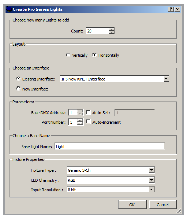
• Enter the number of lights attached to the power/data supply in the Count box.
• Use the Choose an Interface pane to select an existing power/data supply, or add a power/data supply that is not already part of your map.
• Set the Base DMX Address and Port Number. Select the Auto-Set check box to set to the next available DMX address. If you are adding multiple luminaires, select the Auto-Increment check box to increment each node’s DMX address automatically.
• Type a name in the Base Light Name box, or use the default name.
• Use the Fixture Properties pane to match your nodes’ configuration.
- Click OK to add the fixtures to your map. The fixtures are automatically added to the map and appear in the layout panel.
- Save your map by selecting File>Save Map.
To associate a placeholder map:
Creating a placeholder map by manually adding fixtures can save time prior to installation, if you are certain of the layout. Once the installation is complete, you can then quickly synchronize your existing placeholder map with the devices on your lighting network.
- With your computer connected to the lighting network, open the offline map file in Management Tool.
- Click Sync Interfaces in the tool bar, or select Light View>Sync Interfaces from the menu. The Network Sync window is displayed.
- Select whether you want to synchronize using IP address or serial number of your power/data supplies, and then click Sync.
When you click Sync, Management Tool scans your lighting network. If Management Tool finds power/data supplies that match those in your placeholder map, those power/data supplies become associated with the devices on your placeholder map, and Management Tool then attempts to associate any luminaires attached to those power/data supplies.
If any devices could not be associated, continue to the following procedure to associate individual devices, one at a time.
To associate an individual power/data supply:
- In the Light/Interfaces pane, right-click an offline power/data supply, and then click Associate with Discovered Interface. The Associate Interface window is displayed.
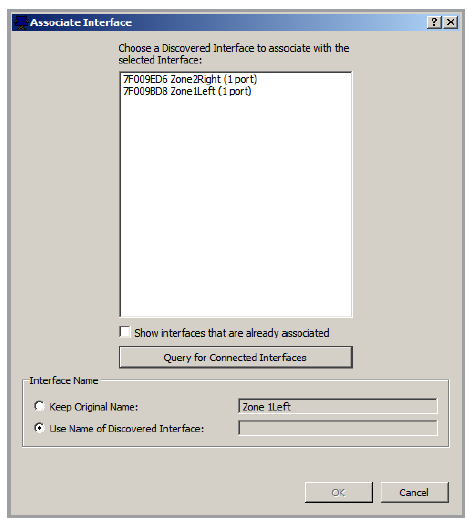
- If no discovered power/data supplies are shown, ensure that your computer is connected to the lighting network, and then click Query for Connected Interfaces.
- Select the intended interface, and then click OK.
2. Map Layout and Groups
Editing the Map Layout
When you have created a map by discovering KiNET interfaces and fixtures with the Management Tool, you are ready to fine-tune the position and orientation of fixtures in the map layout panel.
In the layout panel, fixtures appear as black icons in the order that they were added to the map. You can move the fixture icons, change their order, and create groups to organize your installation.
Select Nodes
There are three ways to select nodes: capture, pick, and sweep.
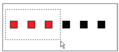
To use Capture selection:
• To capture a group nodes, drag an enclosure box around the intended nodes. Node icons turn red when they are selected.
• To deselect all nodes, click a blank area away from the selected icons.
To use Pick selection:
• To select a single node, click that node.
• To select multiple nodes, hold down Ctrl (Windows) or Command (Mac) while clicking additional node icons.
• To deselect all nodes, click a blank area away from the selected icons.
To use Sweep selection:
• To select nodes using a sweep line, position the cursor at the pivot point of the fan line, and then hold Alt while clicking the left mouse button. Drag the cursor away from the pivot point to select additional nodes. Node icons turn red as the sweep line passes over them.
• To deselect all nodes, click a blank area away from the selected icons.
Edit Position and Orientation
To move nodes:
Select the intended node icons, and then drag the selected group to a new location.
To rotate a selection:
Select the nodes to be rotated, rick-click the select selection, and then click Rotate Selection CW (clockwise) or Rotate Selection CCW (counterclockwise) from the command menu.
Groups
Now that you’ve mapped your devices and arranged your layout, the last step in refining your map is to create groups.
• Groups determine how light show effects are associated with your luminaires. To apply an effect to a luminaire, the nodes in that luminaire must be in a group.
• There are two types of groups: synchronized groups and chasing groups. The order in which effects move across your nodes is determined by their group type.
Group Type | Description |
Synchronized group | The nodes work in unison to display the same output. |
Chasing group | Nodes in a chasing group work in series, in the order of their position within the group. For example, the first node in the group acts as fixture 1, the second node as fixture 2, and so on. Chasing groups enable animated effects to appear to chase from one node to another, then to another, and so on. |
Create Groups
Groups are collections of nodes to which you can apply lighting effects. The static scene creator in the iPlayer 4 web interface apply effects to the groups you define in your map file. You must create a group for each collection of lights you want to control in ColorPlay 4 or iPlayer 4.
To create a group from the Layout panel:
- From the layout panel, select the nodes to be included in the group.
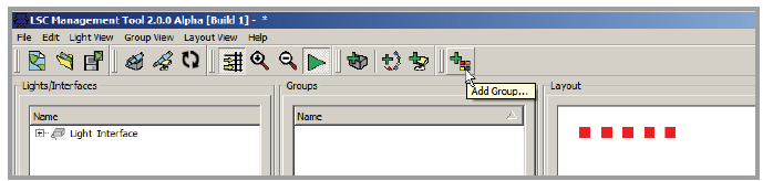
- Click the Add Group icon from the tool bar, or select Group View>Add Group from the menu. The Create Group window is displayed.
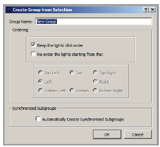
- When the Group Editor opens, select light ordering for the group. The light numbering order determines the sequence in which chasing effects will be displayed.
- Click OK. The new group is added to the Groups panel in the Management Tool.
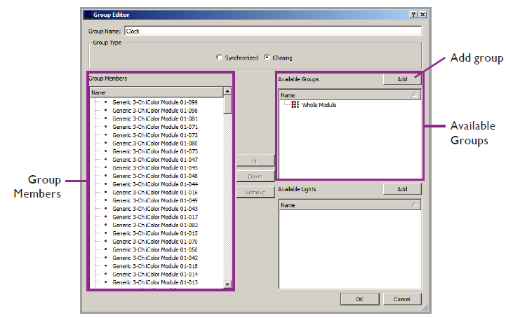
To edit a group:
- Double-click a group in the Groups panel. The Group Editor window is displayed. with a list of available nodes in the lower right panel.
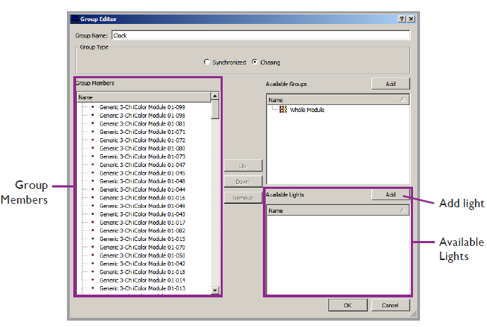
- Select the lights to be added to the new group, then click Add. The lights move from the Available Lights panel to the Group Members panel.
- Use the Up, Down, and Remove buttons to arrange highlighted nodes in the desired order.
- Rename the group, as necessary, select the group type, and then click OK.
To create a group within a group:
- Double-click a group in the Groups panel. The Group Editor window is displayed. with a list of available nodes in the lower right panel.
- Select the lights to be added to the new group, then click Add. The lights move from the Available Lights panel to the Group Members panel.
- 3. Use the Up, Down, and Remove buttons to arrange highlighted nodes in the desired order.
- 4. Rename the group, as necessary, select the group type, and then click OK.
Animation Template
For animated effects, an animation template is useful for maintaining the aspect ratio of a sequence of images. Using a template ensures that you get the desired visual effect without a skewed or stretched appearance.
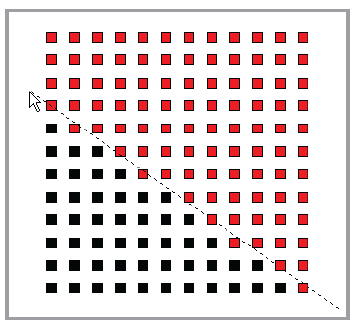
Grouping Nodes for an Animated Effect
When grouping nodes for an animated effect, consider the desired visual effect. For example, if you want the animated effect to play on individual nodes, create separate groups for each node. If you are using a rectangular array of Flex Compact gen3, RGB nodes configured as a single viewing surface, create a group that includes all of those nodes.
To create an animation template:
- After arranging the light icons in the Lights panel to match the installation, select Layout View>Create Animation Template.
- Enter a file name at the prompt, then click Save. The template grid size dialog box appears.
- Enter a grid size and click OK. You now have a template that you will insert into your animation file as a layer and use as a size guide for creating animation files.
- Format your animation to fit the template.
- Select Edit>Save Map to save your work.
3. Introduction to ColorPlay 4
When you have mapped your installation and assigned the fixtures to groups in Management Tool, you are ready to create a light show by applying effects. ColorPlay 4 imports .map files and lets you apply single or multiple effects to groups and edit the various effect properties, creating a custom show.
How Did We Do?