Table of Contents
- QuickPlay Pro 2 and the Commissioning Process
- Getting Started
- Install QuickPlay Pro 2
- Connecting to a Color Kinetics Lighting System
QuickPlay Pro 2 Quick Start Guide
Use QuickPlay Pro 2 to commission Color Kinetics Lighting Systems.
- QuickPlay Pro 2 and the Commissioning Process
- Getting Started
- Install QuickPlay Pro 2
- Connecting to a Color Kinetics Lighting System
QuickPlay Pro 2 and the Commissioning Process
Welcome to QuickPlay Pro 2 and thank you for using it to commission Color Kinetics Lighting Systems.
The commissioning process involves four Steps:
1. Device Configuration
2. Setup DMX Address Maps
3. Test DMX Address Maps
4. Live Demonstration
QuickPlay Pro 2 is designed to support all the steps in the Commissioning Process, and this document will guide you in its use.
Getting Started
Install QuickPlay Pro 2
QuickPlay Pro 2 is a software application that can be installed on your computer.
QuickPlay Pro 2 Installer is available for Windows and macOS systems.
Download QuickPlay Pro 2 Installer
- Download the Installer from https://www.colorkinetics.com/global/support/qpp2
- Format of the file name for the downloaded file is: QuickPlayPro2-<System Environment>-<Version>-<Date>-<Build>.zip
- System Environment: Supported Environments is indicated in the file name. Win / Mac.
- Version: Version number of the application. For example: 2.0.4
- Date: Reference date when version of application is made available. For example: 20210101
- Build: Reference build number of the application. For example: 1234
- Extract the contents of the Zip file to a suitable location.
- You will notice two files:
- Release_Notes.html – Refer to the information regarding change history of versions.
- QuickPlayPro2Installer – Installer executable.
Install QuickPlay Pro 2 on Windows
Double-click QuickPlayPro2Installer.exe to begin installation and follow the on-screen prompts.
To install software on certain computers, due to the IT restrictions you may have to perform one or more of the following alternative procedures:
- Right-Click and then Click ‘Run as Administrator’ QuickPlayPro2Installer.exe to begin installation and follow the on-screen prompts.
- Consult your IT administrator if the IT policy restrict installation of any software on the computer.
Install QuickPlay Pro 2 on Mac
- Double-click QuickPlayPro2Installer.app to begin installation and follow the on-screen prompts.
Connecting to a Color Kinetics Lighting System
Color Kinetics Lighting Systems can either be a KiNET (Ethernet) Lighting Installation or DMX Lighting Installation.
Connect to a KiNET (Ethernet) Lighting Installation
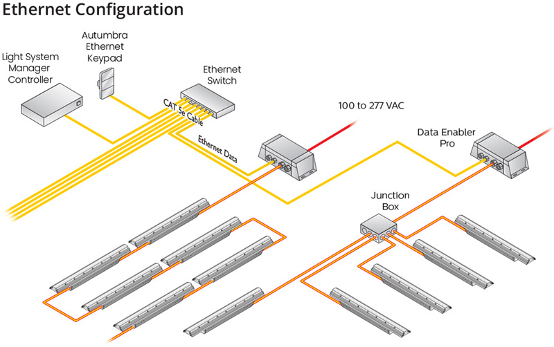
You can connect your computer directly to an Ethernet Switch in the network of the Lighting Installation.
By default, Ethernet devices from Color Kinetics are assigned an IP Address in the 10.x.x.x range. Typically, the lighting network is configured with static IP Addresses in the 10.x.x.x range with Subnet Mask of 255.0.0.0.
You must ensure that your computer is configured with IP Address and Subnet Mask to connect to the lighting network.
Configure Static IP Address to your computer on Windows:
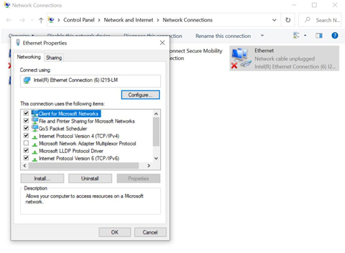
- From the Start menu, select Control Panel, and then double-click Network Connections. The Network Connections window is displayed.
- Double-click the Local Area Connection icon associated with the computer’s integrated network card. Disable your wireless network card and any VPN connections, if applicable.
- In the Local Area Connection Status window, click Properties. The Local Area Connection Properties dialog is displayed.
- Select Internet Protocol (TCP/IP), then click Properties. The Internet Protocol (TCP/IP) Properties dialog is displayed.
- Select Use the following IP address. Enter an IP address of 10.1.2.3 (or another IP address in the 10.x.x.x range) and a Subnet mask of 255.0.0.0.
- Click OK to return to the Local Area Connection Status window, and then click Close.
Configure Static IP Address to your computer on Mac:
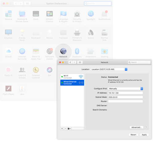
- From the Apple menu or the Dock, open System Preferences, and then click the Network icon.
- From the Location list, select Automatic.
- Select your Ethernet device from the left pane.
- From the Configure IPv4 list, select Manually.
- Enter an IP Address of 10.1.2.3 (or another IP address in the 10.x.x.x range) and a Subnet Mask of 255.0.0.0.
- Click Apply.
Connect to DMX Lighting Installation
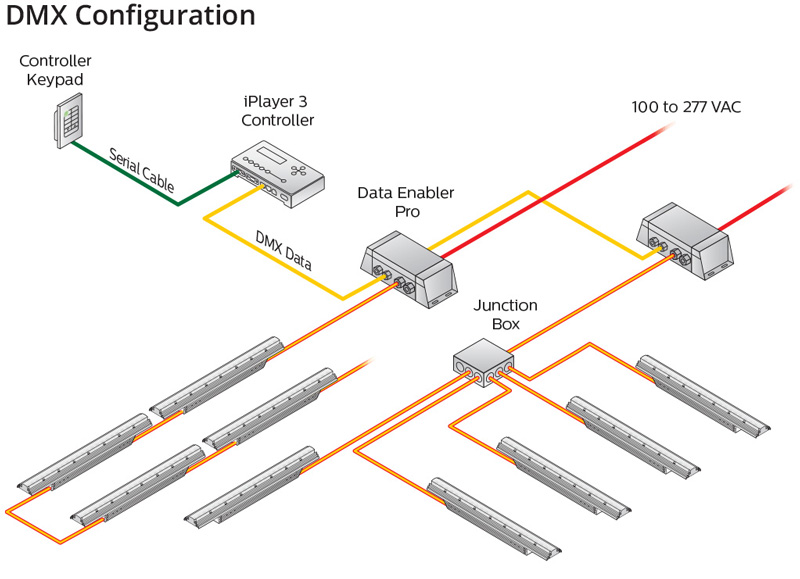
You need a Color Kinetics USB Device like an iPlayer 3 or a SmartJack Pro to connect your computer to a DMX Lighting System.
- Connect the USB Cable between your computer and Color Kinetics USB Device.
- Connect the Color Kinetics USB Device to the DMX Lighting Network.
You have now physically connected your computer to the Color Kinetics Lighting System.
QuickPlay Pro 2 Overview
Key Features of QuickPlay Pro 2
Feature | Description |
Network Topology | Tree based representation of the devices and their hierarchy in the Lighting System. Search, Sort and Filter can be performed on the devices in the tree. |
Network Activity | Overview of current activity on the Lighting Network. This allows the user to see what network activity is occurring, how long it may take to complete, and to continue to use the application while tasks are running. |
Device Configuration | Discover devices to create a network topology. Read properties of the devices to determine the current configuration. Write properties to the devices to set the desired configuration. |
Setup DMX Address Map | DMX Address Map of a PDS can be populated by assigning a range of DMX Addresses to desired light luminaire(s). This setup is completed by writing the assigned DMX Start Addresses to the light luminaire(s). |
Test DMX Address Map | DMX Address Map on one or more PDS can be tested by setting a desired intensity on set of selected channels. |
Live Demonstration | QuickPlay Pro 2 can be used to do a live demonstration of the dynamic lighting effects that can be played on the selected network topology of the system. |
Light Simulation | Light Simulation is a generated visual representation of the light points based on the selected part of the network topology. |
Import/Export Topology | Network Topology can be exported to a csv or map file. Importing a map file can load devices and their properties into the Network Topology. Importing a csv file can be used to perform a bulk write of IP Addresses to ethernet devices and/or DMX Addresses to luminaires. |
QuickPlay Pro 2 Tools
Tool | Description |
Tool Selector | Displays the list of functional tools – Settings, Address, Test, Effects |
Device Tree | Device Tree tool is used to work with the Network Topology. It is the core tool used to select the scope of operation in all the other tools. |
Tool Widget | Displays the main control area of the selected tool. |
Settings Tool | Settings Tool is used to work on the configuration of selected device(s) in Network Topology. |
Address Tool | Address Tool is used to setup DMX Address Map on a selected ethernet device or USB device. |
Test Tool | Test Tool is used to test DMX Address Map on selected (single or multiple) ethernet device or USB device. |
Effects Tool | Effects Tool is used to play a live demonstration of a desired light effect on selected device(s) in Network Topology. |
QuickPlay Pro 2 Layout
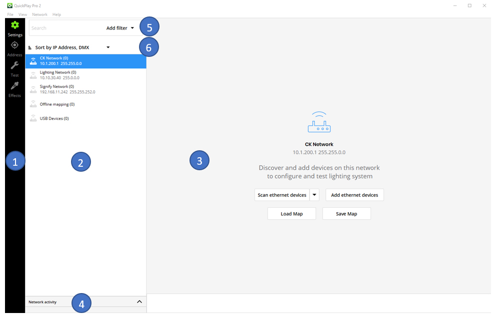
- Tool Selector
- Device Tree
- Tool Widget
- Network Activity Monitor
- Device Search and Filter Options
- Device Sort Options
Network Topology
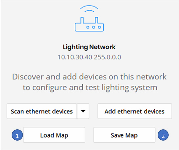
First step in commissioning is to create a network topology of the installed lighting system. Network Topology can be created in Online Mode, Import Mode or Offline Mode using the Settings Tool.
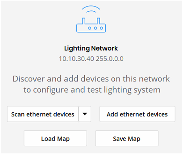
Create Network Topology in Online Mode
- Click on ‘Settings Tool’ in the Tool Selector.
- Available Networks are displayed in the Device Tree.
- Click to select a desired network to start creating network topology.
- Click on ‘Scan ethernet devices’.
- Initiates a discovery of all ethernet devices in lighting network.
- Reads Properties from all the discovered ethernet devices.
- This usually takes only a few seconds to complete.
- Device Tree is populated with the discovered ethernet devices.
- Network Activity shows the progress of the scan.
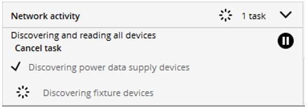
- (Optional) Click on ‘Scan all’
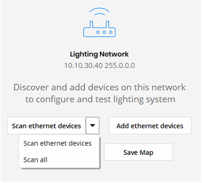
- Initiates a discovery of all ethernet devices in lighting network.
- Initiates a discovery of all luminaires on each discovered ethernet device.
- Reads Properties from all the discovered devices (PDS and Luminaires).
- This may take several minutes to complete depending on the size of the installation.
- Device Tree is populated with the hierarchy of discovered ethernet devices and luminaires
- Network Activity shows the progress of the scan.
- If Step 5 is NOT performed, perform the following steps to continue creating Network Topology.
- In Device Tree, click to select ethernet device(s).
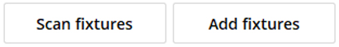
- Tool Widget area displays two options – Scan Luminaires, Add Luminaires.
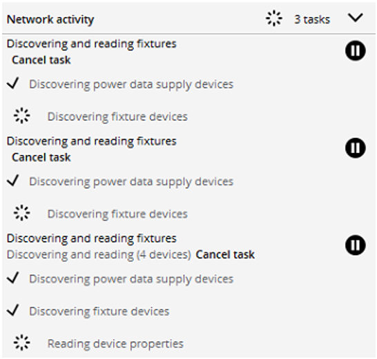
- Click ‘Scan Luminaires’.

- Initiates a discovery of all luminaires on each selected ethernet device.
- Reads Properties from all the discovered luminaires.
- This may take several minutes to complete depending on the size of the installation.
- Device Tree is populated with the hierarchy of ethernet devices and discovered luminaires.
- Network Activity shows the progress of the scan.
- Step 6 can be performed on multiple selections of one or more ethernet device(s) in Device Tree simultaneously.
Create Network Topology in Import Mode
- Click on ‘Settings Tool’ in the Tool Selector.
- Available Networks are displayed in the Device Tree.
- Click to select a desired network to start creating network topology.
- Click on ‘Load Map’.

- Select a valid (previously exported) map file in open file dialog.
- Device Tree is populated with the hierarchy of ethernet devices and luminaires from the map file.
Create Network Topology in Offline Mode
- Click on ‘Settings Tool’ in the Tool Selector.
- Available Networks are displayed in the Device Tree.
- Click to select a desired network to start creating network topology.
- Click on ‘Add ethernet devices’.

- Follow the instruction on the prompt to add ethernet device(s).
- Device Tree is populated with the new ethernet devices.
- In Device Tree, click to select ethernet device.
- Tool Widget area displays two options – Scan Luminaires, Add Luminaires.
- Click ‘Add Luminaires’.
- Follow the instruction on the prompt to add luminaire(s).
- Device Tree is populated with the new luminaire(s) under the selected ethernet device.
- Repeat Step 4 and Step 5, to complete creation of Network Topology.
Now you have a Network Topology ready for the next steps in commissioning.
Search Devices in Network Topology
Start by selecting and entering text into the input field. This will show matching strings (in bold) of the name, serial, or IP address after 2+ characters are entered. When there are matching luminaires, the parent device are also shown in the results indicating device hierarchy.
Filter Devices in Network Topology
The user selects the input field, and the 'Add filter' dropdown button is shown. The dropdown contains the following filter options:
1. Device type
2. Firmware version
When a filter is added, a row appears below the search field where the user can select the value for each filter. The values shown represent all the available values in the device set. By default, no value is selected. After a value is selected, the results with matching properties are displayed. Any input text in the search field is combined with the filters when producing results. After a filter is added, it is removed from the 'Add filter' dropdown. If all possible filters have been added, the 'Add filter' dropdown is disabled.
When a filter is removed using the '-' button, the criteria are removed from the search and the matching results are updated.
Sort Devices in Network Topology
There is a sort order menu and a single toggle selection for ascending/descending order. When devices are reordered, the device hierarchy is always preserved - child devices always appear under the corresponding parent device. Networks are not sortable and appear in the default system order always. The sort options from the menu are:
- Ethernet devices
- IP address (default)
- Name
- Serial
- Type
- Luminaires
- DMX (default)
- Serial
- Name/Type
- Location
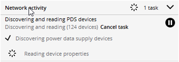
Network Activity
Activity is displayed in an expandable panel at the bottom of the device tree titled "Network activity".
- Panel is only visible when there is network activity.
- Panel by default opens to auto-height (height of content + padding).
- Panel can be collapsed to show the title bar only and maintains this state until expanded by the user.
- Panel title bar includes the number of active + pending tasks, e.g., "2 tasks."
- Panel title bar indicates when light data is being sent, e.g., "Sending light data".
- Panel shows active and pending tasks only, completed tasks are removed.
- If a task completes with an error, the error indicator and activity panel remain until dismissed by the user.
The panel displays tasks that are either triggered by the user explicitly (e.g., user selects "Scan devices") or implicitly (e.g., the user navigates to the "Test" Tool and lights are set to dark).
Types of tasks
The following tasks appear independently in the activity monitor:
- Scan
- Read Properties
- Apply Settings
- Update firmware
Sending light data is indicated in the activity panel title bar but is not shown as a task.
Task states
Each type of task has the following distinct states:
- Active
- Paused. Paused by user or tasks automatically get paused when there is an interfering network activity (e.g., sending light data).
- Error - tasks completed with errors or tasks cancelled.
Task actions
- Active tasks can be paused.
- Paused by user tasks can be resumed.
- Active and paused tasks can be cancelled.
- Cancelled and Error tasks can be removed.
Task information
All tasks indicate the following information in the task description, detailed in the table below:
- Type of task (e.g., Scan, Read, Apply settings, Update firmware)
- Status of task (e.g., Active, Paused, Error)
- Subject name (if single) or # of subjects (if multiple)
1. Device Configuration
Device Configuration is the first step in the commissioning process. Device configuration is done using the Settings Tool of QuickPlay Pro 2.
Overview of Settings Tool
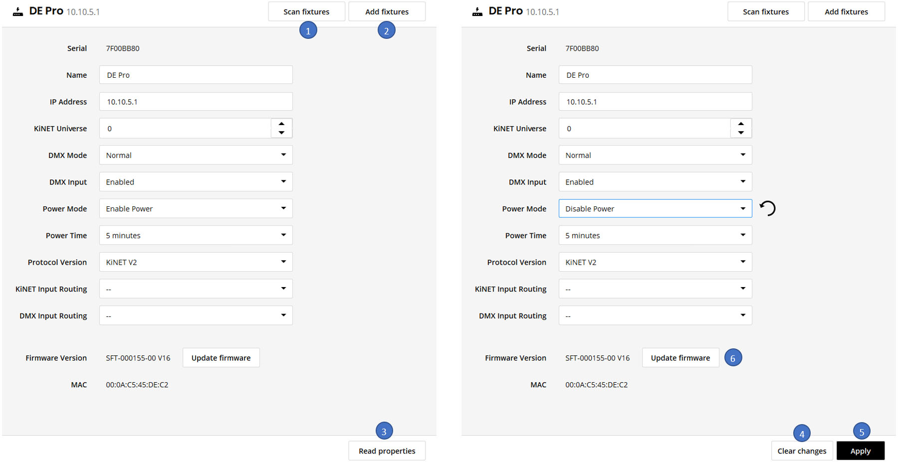
Settings Tools offers the following functions to assist with configuring device(s):
- Scan Luminaires
- Add Luminaires
- Read Properties
- Apply (Apply Configuration Settings)
- Clear Changes
- Firmware Update
Settings Tool offers the same Tool Widget Layout for all types of devices. Types of devices and the tools available are summarized below:
Device Type | Tools Available for Device Configuration |
Ethernet Devices | Device Tree – To be able to select one or more ethernet devices. Scan Luminaires– To be able to discover and read properties of connected luminaires. Add Luminaires– To be able to manually add luminaire(s) to selected ethernet device. Read Properties – To be able to read properties from the selected ethernet device(s). Apply – To apply the changes to the selected ethernet device(s). Clear Changes – To clear the changes. Firmware Update – If supported, Update the firmware of the selected ethernet device (One at a time). |
Powercore Luminaires | Device Tree – To be able to select one or more luminaires. Read Properties – To be able to read properties from the selected luminaire(s). Apply – To apply the changes to the selected luminaire(s). Clear Changes – To clear the changes. Firmware Update – If supported, Update the firmware of the selected ethernet device(s). |
XMX Luminaires | Device Tree – To be able to select one or more luminaires. Read Properties – To be able to read properties from the selected luminaire(s). Apply – To apply the changes to the selected luminaire(s). Clear Changes – To clear the changes. Firmware Update – If supported, Update the firmware of the selected ethernet device(s). |
RDM Luminaires | Device Tree – To be able to select one or more luminaires. Read Properties – To be able to read properties from the selected luminaire(s). Apply – To apply the changes to the selected luminaire(s). Clear Changes – To clear the changes. Firmware Update – If supported, Update the firmware of the selected ethernet device(s). |
Chromasic Nodes | Chromasic nodes are not configurable. |
Overview of Properties commonly used in Device Configuration
Color Kinetics Devices – Ethernet PDS, Ethernet Luminaires, Powercore Luminaires, FlexElite Luminaires, and RDM Luminaires offer a variety of properties as part of Device Configuration. QuickPlay Pro 2 displays the available properties in the Device Type for Device Configuration in the Settings Tool as a unified layout irrespective of the Device Type.
The following table summarizes most used properties in Device Configuration across different Device Types:
Property | Description |
DMX Address | Set the starting DMX Address for the luminaire. |
Light Number | Applies to PDS with Chromasic Nodes and Accent Powercore luminaires. Indicates the starting index (zero based) to be used for the Connected Chromasic Nodes. Automatically assigns a range of DMX Addresses to the Chromasic Nodes in a sequence starting from the DMX Address calculated based on Light Number. Starting DMX Address = (Light Number X 3) + 1. For example: If you assign a Light Number 40. And there is a 20 Chromasic Node String. DMX Addresses (121 to 180) in the DMX Address Map (1 – 512) will be assigned to this Chromasic nodes in sequence. |
KiNET Universe | Universe addresses shall only be applied to Art-NET, sACN, and KiNET DMX OUT packets. KiNET Port Out packets are sent directly to each physical port. The universe address shall have a range of 0-65535 with the default of 0 for all ports. |
Port ‘N’ Universe | Universe addresses shall only be applied to Art-NET, sACN, and KiNET DMX OUT packets. KiNET Port Out packets are sent directly to each physical port. The universe address shall have a range of 0-65535 with the default of 0 for all ports. |
DMX Mode | Normal or Backwards Compatible. |
DMX Input | Enable - Sends data on DMX Interface of Data Enabler Pro. Disable - Stops sending data on DMX Interface of Data Enabler Pro. |
Protocol Version | KiNET version used for output light data. |
Scale Factor | Scale factor of the power output to Chromasic nodes. Range: 1- 255 |
Pixel Resolution | Certain direct view luminaires offer a variable pixel (node) size. |
Factory Node Count | Number of Chromasic nodes in the product. |
Current Node Count | Discovered count of Chromasic Nodes. |
Enable Bootloader | Enable - Set the device in bootloader mode to allow firmware update. Disable - Set device in normal operation mode. |
Subnet Mask | Subnet Mask to be used by the ethernet device. |
Power Mode | Enable Power Disable Power Turn off after no data for timeout period. Turn off after black data for timeout period. |
Power Time | Timeout to be used in case Power Mode is set to turn off after a timeout. |
Resolution | 8-bit or 16-bit Color Data Resolution. |
Color Control Mode | N Ch In/Out: The luminaire accepts four or five channels of DMX data. Allows for direct control of each individual LED channel. Chromasync is disabled. 3 Ch In/Out: The luminaire accepts three channels of DMX data. Additional channels are disabled. Chromasync is disabled. 3 Ch In/4 Ch Out + Chromasync: The luminaire accepts three channels of DMX data. Sends output to four or five LED channels. Chromasync is enabled. N Ch In/Out + Chromasync: The luminaires accepts four or five channels of DMX data. Sends output to all four or five LED channels. Chromasync is enabled. 3 Ch In/Out + Chromasync: The luminaire accepts three channels of DMX data. Sends output to the RGB LED channels. Chromasync is enabled. |
Chromasync Mode | Enable - This setting ensures advanced consistency between this and other Chromasync-enabled luminaires in the same product family. Disable - This setting gives direct control of LED channels. |
IW Input Mode | For some IntelliWhite luminaires, this setting determines whether two or three DMX channels are used to control the luminaire. |
White Point Optimization | This list is only available when Chromasync is enabled. When rendering whites along the black-body curve, this setting determines whether the luminaire should produce a color that prioritizes CRI or brightness. Select CRI to enhance CRI. Select Flux to prioritize brightness. |
Led Speed | Normally, LEDs react to DMX or other control data instantaneously. In some cases, you may want to slow down the reaction speed to achieve smoother transitions when the intensity of different LED channels changes. Fast - Sets instant LED reaction to control data. Delay-1 (shortest delay) – Delay-4 (longest delay) for smoother transitions. |
Dimming Curve | Normal - Use this dimming curve to achieve consistent dimming behavior in an installation where the luminaire is installed alongside other Color Kinetics luminaires that don’t have dimming curve functionality. Tungsten - A non-linear dimming curve that emulates the dimming curve of incandescent lamps on a DMX dimmer. This curve offers the most control at low intensities. Linear - A dimming curve with a linear relationship between DMX input and LED power. |
Livescan | Disable - Lights to blink rapidly when they receive/send configuration data. Enable - Lights do not blink when they receive/send configuration data. We recommend leaving this option Enabled at all times other than commissioning. |
2. Setup DMX Address Maps
This feature enables each device in the lighting system to extract the segment of data that is targeted for a luminaires address, so that each luminaire displays the correct light output from the DMX Light Data.
The Address Tool of QuickPlay Pro 2 helps set up the DMX Address Maps.
Overview of the Address Tool
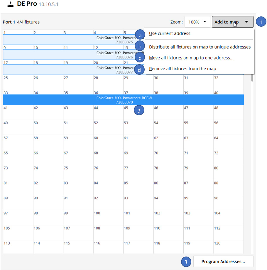
Address Tool offers the following functions to set up the DMX Address Map:
- Add to map
- Use current address
- Distribute all luminaires on map to unique addresses
- Move all luminaires on map to one address
- Remove all luminaires from the map
- Select Luminaire(s)
- Program Addresses
Device Tree offers the following functions to Setup the DMX Address Map:
- Select Device(s)
- Select Ethernet Device
- Select a Port on Ethernet Device
- Select Luminaire(s)
- Drag and Drop selected Luminaire(s) to the DMX Address Map
Workflow to Setup DMX Address Map
Action | Result |
Select Ethernet Device | Device Tree: • If the Ethernet Device has multiple ports, Port 1 gets selected by default. Address Tool: • If there was a pending DMX Address Map waiting to be Programmed, a warning message is displayed. • DMX Address Map context is set to the current selection on Device Tree. |
Select a Port on Ethernet Device | Device Tree: • Parent Ethernet Device is selected. Address Tool: • If there was a pending DMX Address Map waiting to be Programmed, a warning message is displayed. • DMX Address Map context is set to the current selection on Device Tree. |
Select Luminaire(s) | Device Tree: • Parent Port is selected. • Parent Ethernet Device is selected. Address Tool: • If there was a pending DMX Address Map waiting to be Programmed, a warning message is displayed. • DMX Address Map context is set to the current selection on Device Tree. Lighting Network: • Powercore Luminaires: Highlight in green. If multiple luminaires are selected, they are highlighted in green one at a time. Highlight goes on in loop. • FlexElite Luminaires: Highlight in green. If multiple Luminaires are selected, they are highlighted in green one at a time till all the selected luminaires are highlighted. • RDM Luminaires: Blink in white. If multiple luminaires are selected, they start blinking one at a time till all the selected luminaires are highlighted. • Chromasic Luminaires: Not Supported for Setup DMX Address Map using Address Tool. |
Drag and Drop selected Luminaire(s) onto the DMX Address Map | Address Tool: • DMX Address Map is populated. • Sequence of the luminaires on DMX Address Map is based on their order in Device Tree. |
Add to Map | Address Tool: • DMX Address Map is populated depending on selected option. • Available Options: • Use current Address. • Distribute all luminaires to unique DMX addresses. • Move all luminaires to one DMX address. • Remove all luminaires from the map. |
Program Addresses | Lighting Network: • DMX Addresses are written to the luminaires. • Only the changes are written. |
3. Test DMX Address Maps
Test DMX Address Map allows you to validate your installation by sending light data to individual DMX channels, or blocks of DMX channels, and verifies that the corresponding luminaires are illuminated.
Test Tool can be used to test the DMX Address Maps of the installation.
Overview of Test Tool
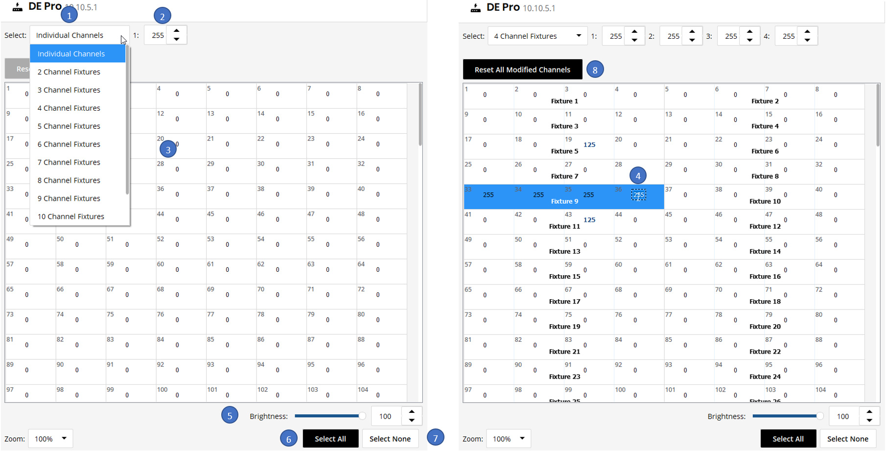
Test Tools offers the following functions to Test DMX Address Map:
- Select Channel Stride
- Preset Channel Value(s)
- Click DMX Block
- Double Click on DMX Channel
- Brightness
- Select All
- Select None
- Reset All Modified Channels
Device Tree offers the following functions to Setup DMX Address Map:
- Select Ethernet Device(s)
- Select Port(s) on Ethernet Device
Workflow to Test DMX Address Map
Action | Result |
Select Ethernet Device(s) | Test Tool: • DMX Address Map context is set to the current selection on Device Tree. Lighting Network: • DMX Data based on current state of DMX Address Map is sent to all the Ports on the Selected Ethernet Device(s) at 40 fps. |
Select a Port(s) on Ethernet Device | Device Tree: • Parent Ethernet Device is selected. Test Tool: • DMX Address Map context is set to the current selection on Device Tree. Lighting Network: • DMX Data based on current state of DMX Address Map is sent to the Selected Port(s) on the Ethernet Device at 40 fps. |
Select Channel Stride | Test Tool: • Sets the Clickable DMX Block to the Selected Channel Stride. |
Preset Channel Value(s) | Test Tool: • Sets the preset value for the DMX Block. |
Click DMX Block | Test Tool: • Updates the DMX Address Map with the Preset Value set on the DMX Block. Lighting Network: • DMX Data based on current state of DMX Address Map is sent to the Selected Port(s) on the Ethernet Device at 40 fps. |
Double Click on DMX Channel | Test Tool: • Makes DMX Channel editable to set a value. • Park the DMX Channel at value. • Makes the DMX Channel Independent of the Preset Channel Value(s). • Makes the DMX Channel Independent of the Brightness. • Makes the DMX Channel Independent of Select All or Select None. Lighting Network: • DMX Data based on current state of DMX Address Map is sent to the Selected Port(s) on the Ethernet Device at 40 fps. |
Brightness | Test Tool: • Updates all the Values on DMX Channel Map proportional to selected brightness. Lighting Network: • DMX Data based on current state of DMX Address Map is sent to the Selected Port(s) on the Ethernet Device at 40 fps. |
Select All | Test Tool: • Updates the DMX Address Map with the Preset Value DMX Block across the entire DMX Address Map. Lighting Network: • DMX Data based on current state of DMX Address Map is sent to the Selected Port(s) on the Ethernet Device at 40 fps. |
Select None | Test Tool: • Resets the DMX Address Map. Lighting Network: • DMX Data based on current state of DMX Address Map is sent to the Selected Port(s) on the Ethernet Device at 40 fps. |
Reset All Modified Channels | Test Tool: • Resets all the DMX Channels parked using “Double Click in DMX Channel”. Lighting Network: • DMX Data based on current state of DMX Address Map is sent to the Selected Port(s) on the Ethernet Device at 40 fps. |
4. Live Demonstration
Live Demonstration is an effective way to complete the commissioning process. It allows you to view the capabilities of the Lighting System, and ensures that the Device Configurations along with the DMX Address Maps worked as expected during the commissioning process delivering the desired result.
The Effects Tool of QuickPlay Pro 2 can be used to do a live demonstration of the Lighting System.
Overview of Effects Tool
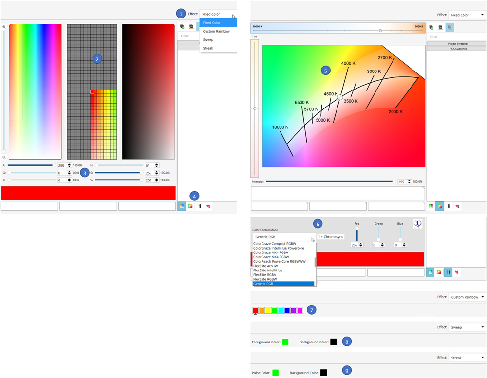
Effects Tools offers the following functions to perform a Live Demonstration:
- Select Light Effect
- Fixed Color Effect
- Custom Rainbow Effect
- Sweep Effect
- Streak Effect
- RGB Color Selector
- RGB Channel Sliders
- Color Spec Selector
- RGB Spec
- White Spec
- NChannel Color Spec
- White – Black Body Curve - Selector
- NChannel Sliders
- Custom Rainbow Effect Parameters
- Sweep Effect Parameters
- Streak Effect Parameters
Device Tree offers the following functions to perform a Live Demonstration:
- Select Network
- Select Ethernet Device(s)
- Select Luminaire(s)
Workflow to Live Demonstration
Action | Result |
Select Network | Effects Tool: • Effect Engine context is set to generate content for the entire Network Topology. Lighting Network: • DMX Data based on the content generated by Effect Engine is sent to the Lighting Network at 40 fps. |
Select Ethernet Device(s) | Effects Tool: • Effect Engine context is set to generate content for the Selected Ethernet Device(s). Lighting Network: • DMX Data based on the content generated by Effect Engine is sent to the Lighting Network at 40 fps. |
Select Luminaire(s) | Device Tree: • Parent Ethernet Device is selected. Effects Tool: • Effect Engine context is set to generate content for the selected luminaire(s). Lighting Network: • DMX Data based on the content generated by Effect Engine is sent to the Lighting Network at 40 fps. |
Select Effect | Effects Tool: • Effect Engine context is set to generate content using selected Light Effect. Lighting Network: • DMX Data based on the content generated by Effect Engine is sent to the Lighting Network at 40 fps. |
Set Color using RGB Color Selector or RGB Channel Sliders | Effects Tool: • Updates the Input RGB Color for the Selected Light Effect. Lighting Network: • DMX Data based on the content generated by Effect Engine is sent to the Lighting Network at 40 fps. |
Set White Color us-ing Black Body Curve | Effects Tool: • Updates the Input White for the Selected Light Effect. Lighting Network: • DMX Data based on the content generated by Effect Engine is sent to the Lighting Network at 40 fps. |
Set Color using RGB Color Selector or N Channel Sliders | Effects Tool: • Updates the Input RGB Color for the Selected Light Effect. • Displays estimated Color Conversion between RGB Color Selector and NChannel Sliders. Lighting Network: • DMX Data based on the content generated by Effect Engine is sent to the Lighting Network at 40 fps. |
Custom Rainbow Effect | Custom Rainbow Effect is useful when showing the dynamic color changing capabilities and Saturated Colors of the Lighting System. |
Sweep Effect | To validate that the DMX Address Map is complete use the Sweep Effect. |
Streak Effect | To validate that the sequence of luminaires is correct in the DMX Address Map use the Streak Effect. |
QuickPlay Pro 2 Hotkeys
Hotkeys in Device tree
Hotkeys | Description |
Up | Moves the cursor to the item in the same column on the previous row. If the parent of the current item has no more rows to navigate to, the cursor moves to the relevant item in the last row of the sibling that pre-cedes the parent. |
Down | Moves the cursor to the item in the same column on the next row. If the parent of the current item has no more rows to navigate to, the cursor moves to the relevant item in the first row of the sibling that follows the parent. |
Left | Hides the children of the current item (if present) by collapsing a branch. |
Right | Reveals the children of the current item (if present) by expanding a branch. |
Minus | Same as Left. |
Plus | Same as Right. |
Asterisk | Expands the current item and all its children (if present). |
PageUp | Moves the cursor to the top of the model. |
PageDown | Moves the cursor to the end of the model. |
Home | Same as PageUp. |
End | Same as PageDown. |
Ctrl + A | Select all items. |
Shift + Up | Adds the item above to the selected ones. |
Shift + Down | Adds the item below to the selected ones. |
Shift + Left | Hides the children of the current item (if present) by collapsing a branch (every second click) and unselected it. |
Shift + Right | Reveals the children of the current item (if present) by expanding a branch (every second click) and selected it. |
Alt + E | Discovering and reading PDS devices. |
Alt + D | Read Devices (Works for both PDSs and Luminaires). |
Alt + L | Discovering and reading Luminaire (Works for PDSs). |
Alt + F | Open File menu and shift focus to menu |
Alt + V | Open View menu and shift focus to menu |
Alt + N | Open Network menu and shift focus to menu |
Alt + H | Open Help menu and shift focus to menu |
Alt + S | Select Settings tab and shift focus to settings |
Alt + A | Select Address tab and shift focus to address map |
Alt + T | Select Test tab and shift focus to test page |
Alt + X | Select Effects tab and shift focus to effects page |
Alt + P | Shift focus to device tree |
Alt + M | On the Address page, open "Add to Map" menu and shift focus to menu |
N | In the device tree, when the address page is active, add selected device to address map at the next available address. Note that this does not take into account the number of channels required for the fixture, so overlapping channels are possible. |
C | In the device tree, when the address page is active, add selected device to address map at current address |
Tab | Move to next selectable property |
Shift-Tab | Move to previous selectable property |
ESC | Select none / clear selection (On all pages except Settings) |
Hot Keys in Settings Tool
Hotkeys | Description |
Ctrl + A | Select all. |
Ctrl + C | Copy selected text. |
Ctrl + V | Paste copied text. |
Ctrl + Z | Undo. |
Ctrl + Y | Redo. |
Ctrl + X | Cut selected text. |
Tab | Move backward to the previous item in the page. |
Shift + Tab | Move backward to the previous item in the page. |
Up | Change values in SpinBox and ComboBox. |
Down | Change values in SpinBox and ComboBox. |
Left | Navigation through the text in LineEdit. |
Right | Navigation through the text in LineEdit. |
Hot Keys in Address Tool
Hotkeys | Description |
Ctrl + A | Select all. |
Ctrl + C | Copy selected text. |
Ctrl + V | Paste copied text. |
Ctrl + Z | Undo. |
Ctrl + Y | Redo. |
Ctrl + X | Cut selected text. |
Tab | Move forward to the next item in the dialog. |
Shift + Tab | Move backward to the previous item in the dialog. |
Up | Change values in ComboBox if it's selected. |
Down | Change values in ComboBox if it's selected. |
Ctrl + Plus | Zoom in. |
Ctrl + Equals | Zoom in. |
Ctrl + Minus | Zoom out. |
Ctrl + Underscore | Zoom out. |
Left | Navigation through the map. |
Right | Navigation through the map. |
Up | / |
Down | / |
Delete | Removes selected |
Hot Keys in Test Tool
Hotkeys | Description |
Ctrl + A | Select all. |
Ctrl + C | Copy selected text. |
Ctrl + V | Paste copied text. |
Ctrl + Z | Undo. |
Ctrl + Y | Redo. |
Ctrl + X | Cut selected text. |
Tab | Move forward to the next item in the dialog. |
Shift + Tab | Move backward to the previous item in the dialog. |
Ctrl + Plus | Zoom in. |
Ctrl + Equals | Zoom in. |
Ctrl + Minus | Zoom out. |
Ctrl + Underscore | Zoom out. |
Shift + Left | Select next item in the DMX map. |
Shift + Right | Select previous item in the DMX map. |
Left | Navigation through the DMX map. |
Right | Navigation through the DMX map. |
Delete or Backspace | Both return a selected intensity value to the global setting |
Hot Keys in Effects Tool
Hotkeys | Description |
Ctrl + A | Select all. |
Ctrl + C | Copy selected text. |
Ctrl + V | Paste copied text. |
Ctrl + Z | Undo. |
Ctrl + Y | Redo. |
Ctrl + X | Cut selected text. |
Tab | Move forward to the next item in the dialog. |
Shift + Tab | Move backward to the previous item in the dialog. |
Ctrl + Plus | Zoom in (Color Picker window). |
Ctrl + Minus | Zoom out (Color Picker window). |
Left | Navigation through the Color Picker. |
Right | Navigation through the Color Picker. |
Shift + Left | In working with the text (selecting text). |
Shift + Right | In working with the text (selecting text). |
Ctrl + 1 | Selects a color from window number 1. |
Ctrl + 2 | Selects a color from window number 2. |
Ctrl + 3 | Selects a color from window number 3. |
Ctrl + R | Increase the red color. |
Ctrl + Shift + R | Decrease the red color. |
Ctrl + G | Increase the green color. |
Ctrl + Shift + G | Reduce the green color. |
Ctrl + B | Increase the blue color. |
Ctrl + Shift + B | Reduce the blue color. |
Import/Export Topology
Commissioning Data can be persisted and retrieved using Import/Export functions. QuickPlay Pro 2 supports Import/Export of Network Topology into CSV or map formats.
Overview of Import/Export of map files
Settings Tool provides the following functions to be able to import/Export map files:
- Load Map
Ability to load a map file and populate Device Tree with Network Topology. Once the Device Tree is populated, all the loaded devices will be marked in disabled state.
‘Scan ethernet devices’, ‘Scan all’, ‘Scan Luminaires’ or ‘Read Devices’ functions in Settings Tool must be used to read latest information from the devices on the network.
- Save Map
Entire Device Tree and the Device Configurations will be exported into the map file.
The map files are compatible with Authoring Tools.
Overview of Import/Export of CSV Files
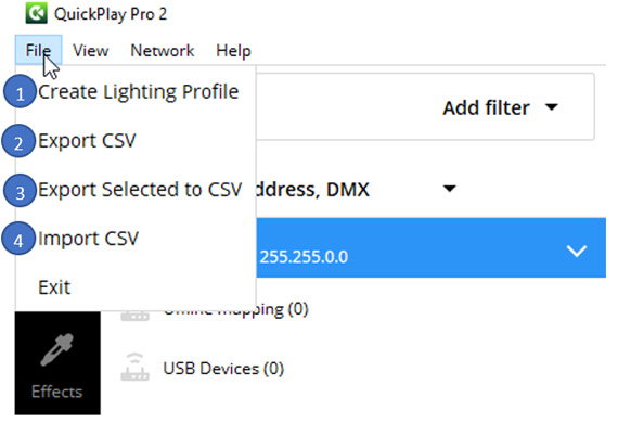
Import and export CSV files using the File Menu in QuickPlay Pro 2.
- Create Lighting Profile
- Creates a CSV file.
- Entire Device Tree is exported.
- Compatible to import the topology into ActiveSite.
- First row in the exported CSV is the header indicating the comma separated fields used in the file.

- Export CSV
- Creates a CSV file.
- Entire Device Tree is exported.
- Compatible to import the topology into ActiveSite.
- First row in the exported CSV is the header indicating the comma separated fields used in the file.

- Export Selected to CSV
- Creates a CSV file.
- Selected Devices in Device Tree is exported.
- Compatible to import the topology into ActiveSite.
- Same format as previous CSV.
- Import CSV
When you import a .csv file, the values in the file will be programmed to the devices on the network.
Names and IP addresses can be edited for Ethernet devices like Data Enabler Pro and Accent Powercore using csv import.
DMX address can be edited for compatible Powercore and low voltage luminaires.
Format of the imported CSV must be as follows:

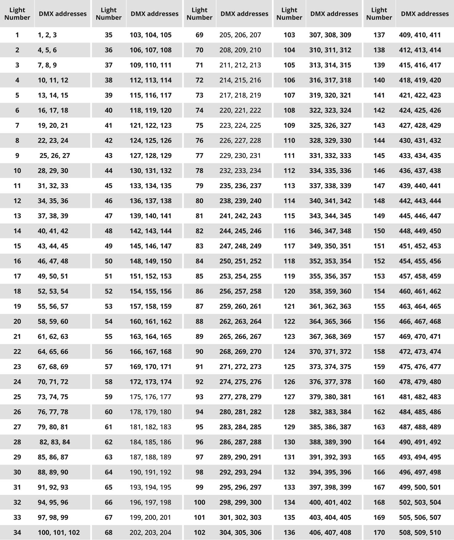
Appendix A
Three-Channel Configuration
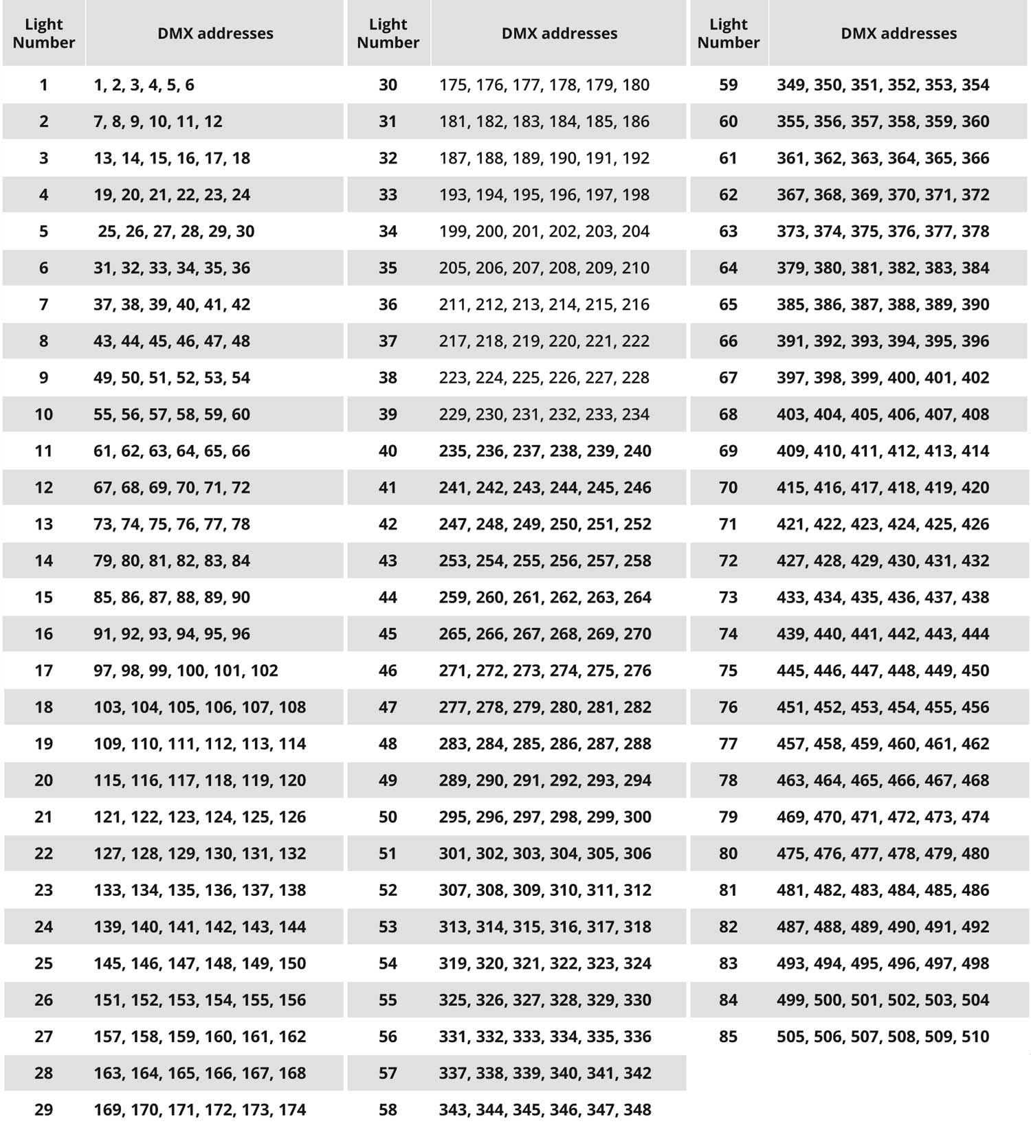
Six-Channel Configuration
Appendix B
CKDMX/ESTA DMX Crossover Cable
A CKDMX to ESTA DMX crossover cable is required when using non-CKDMX controllers with RJ-45 DMX output ports in conjunction with luminaires and power/data supplies from Color Kinetics. The crossover cable installs inline between the controller and the first power/data supply in the DMX lighting installation.
Pin Assignments
CKDMX Male Connector Pin Assignment | ESTA Female Connector Pin Assignment |
8 | 6 |
7 | 3 |
6 | 8 |
5 | 5 |
4 | 4 |
3 | 7 |
2 | 1 |
1 | 2 |
Appendix C
16-bit DMX Channel Mapping
Certain luminaires from Color Kinetics can be programmed for 16-bit control. 16-bit programming utilizes two DMX channels per LED channel: two DMX channels for red, two DMX channels for green, and two DMX channels for blue.
The first DMX channel assigned to an LED channel corresponds to the “coarse” data for that LED channel. The second DMX channel corresponds to the “fine” data for that LED channel.
Utilizing both coarse and fine DMX channels for each LED channel increases resolution from 256 dimming steps per LED channel to 65536 dimming steps per LED channel.
Example: RGB 16-bit DMX Channel Mapping
DMX address | LED Channel |
n | Red Coarse |
n + 1 | Red Fine |
n + 2 | Green Coarse |
n + 3 | Green Fine |
n + 4 | Blue Coarse |
n + 5 | Blue Fine |
Example: ColorReach Powercore gen2, RGB Channel Totals
DMX Channel Totals | Mode |
3 | Full Mode, 8-bit |
6 | Half Mode, 8-bit |
6 | Full Mode, 16-bit |
12 | Half Mode, 16-bit |
© 2024 Signify Holding. All rights reserved. Specifications are subject to change without notice. No representation or warranty as to the accuracy or completeness of the information included herein is given and any liability for any action in reliance thereon is disclaimed.
How Did We Do?
FlexElite Application Guide